Hi everyone.
The reason I made this thread was to work out what has been damaged on my VESC, I fried a DRV on a hobbyking 4.10 VESC because a phase wire shorted out onto the micro-usb plug while I was riding.
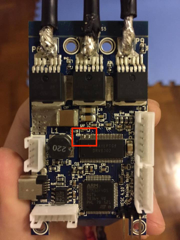
I know that the DRV is fried as there is a black spot on it. I am not sure wether anything else is damaged as well as the DRV chip, since when I power the VESC up, there are no lights that turn on, and when I plug it into the computer the BLDC tool does not recognise it has been plugged in. Does this mean that there is more damage than just the DRV chip?
I bought 3 spare DRV8302DCA chips from Mouser electric, https://au.mouser.com/search/refine.aspx?Ntk=P_MarCom&Ntt=113734323, and am hoping to repair the DRV myself, but I am now thinking that there may be more damage than just the DRV chip.
I am sure one of you VESC guru’s can point me in the right direction. (below are some pics of the VESC)


Cheers
Jake
You will have to replace the drv to see because the drv is responsible for creating the 5v which is turned into 3v3 that the logic(mcu) needs to turn on
After replacing the drv check for short on all lines as well as phase outputs and battery input. If there is no short plug it in and see if the mcu boots
1 Like
That answers my question, thanks a lot!
Do you have any tips for replacing the DRV? This will be my first time doing such a precise soldering job.
Well, dont forget the pad underneath and avoid solder balls getting where they should not be so inspect the PCB throughly before powering it on, also make sure the chip is flat when you solder the pad. With some magnifying glass or a microscope check if all legs of the chip are connected
Ok thanks, with the bottom pad, is the hot air enough to melt the solder that is under the chip? Thanks for the help!
Yeah it is definitely, even more than enough. There is no real rule to how much temperature and time is the max before some damage is done so you will just have to be careful. You can slide the plastic part of the JST connectors off without desoldering the pins that way you wont melt the plastic
1 Like
Thats a good tip about taking off the plastic parts. Thanks for the help, ill be sure to post how it goes 
1 Like
ok, one more question. What temperature would you use on the hot air gun? I’m thinking 250-300C, and would 30 seconds be the limit of hot air exposure for the components?
I use 320C and I think it might take less before the solder melts I am not sure never measured it  It is hard to say because there is a lot of factors to it, like air flow, distance of the nozzle from the component, and the diameter of the nozzle to or the area that the air is focused on.
Before going full temp I suggest you set it to for example to 200C and blow on it for a minute to let the pcb heat up to prevent heat shock (big temperature differences between places on the pcb)
Hi Jake,
solder melt at around 200c, so you should set your heat gun at around 240-250c and make sure your flow of air is as low as you can, you don’t want to see part flying around.
Also check if the resistor R48 to R51 are at 100ohms (give or take 10%).
Regards
JF
Thanks for the info @JohnnyMeduse , I measured those resistors and had an interesting result…
R48: 100.7 ohms
R49: 49.8 ohms
R50: 32 ohms
R51: 4.3 ohms
Im measuring by touching the ends of the multimeter wires at the ends of each resistor as you would. Do you think the resistors are damaged?
Thanks!
HI Jake,
Hmmm, they are all supposed to be 100Ohms but if the DRV is damage it could lead to false measurement, maybe try to measure them once the DRV is remove or replace.
Regards
JF
2 Likes
An update, I managed to replace the DRV which seemed to work, however only the blue light was on after i installed it, no green light. I believe this was due to a faulty processor, so I got my other (very) cooked Vesc and unsoldered the processor off it and soldered it onto the VESC. It worked for a while until I did a motor detection and a mosfet lit on fire  . I knew I was so close to fixing it! so I thought f**k it ill just run the vesc on my single motor on FOC mode so I fry the DRV (I know the DRV always fries with FOC on the SK3 192KV 6364 motor, as this is what fried the other VESC) so as I hoped, the DRV fried within a minute, flashing red light on the VESC and DRV8302 error on the app. So I unsoldered the DRV to replace but in the process I permanently shorted 2 of the pads! so the board was toast
  anyway at least I got good at hot air surface mount soldering!
Thanks again for the guidance @Martinsp @JohnnyMeduse
No need to cook the vesc just because you blew a fet.  Congrats on your drv replacement though.
1 Like
@Jakebarnhill1 What do you mean permanently shorted?
1 Like
2 of the pads for the DRV chip were shorted with solder and I know that you can normally use solder wick and an iron but that didn’t work it seemed to be like the 2 pads joined somehow?
There are two times two pads shorted, it is on pins 53+54 and 51+50. These are supposed to be shorted as you can see on the picture below.
1 Like
ohhhh right…I think i only noticed one shorted, does it work if the second one isn’t shorted?
It is shorted on the PCB anyway so even if it looked like there are no shorts visible, the traces underneath are shorted.
1 Like
Martinsp is correct. Here’s a picture of what the wires look like. You’re looking at 50-51 and 53-54. You’re still in the clear. That VESC may just come back to life yet.
2 Likes