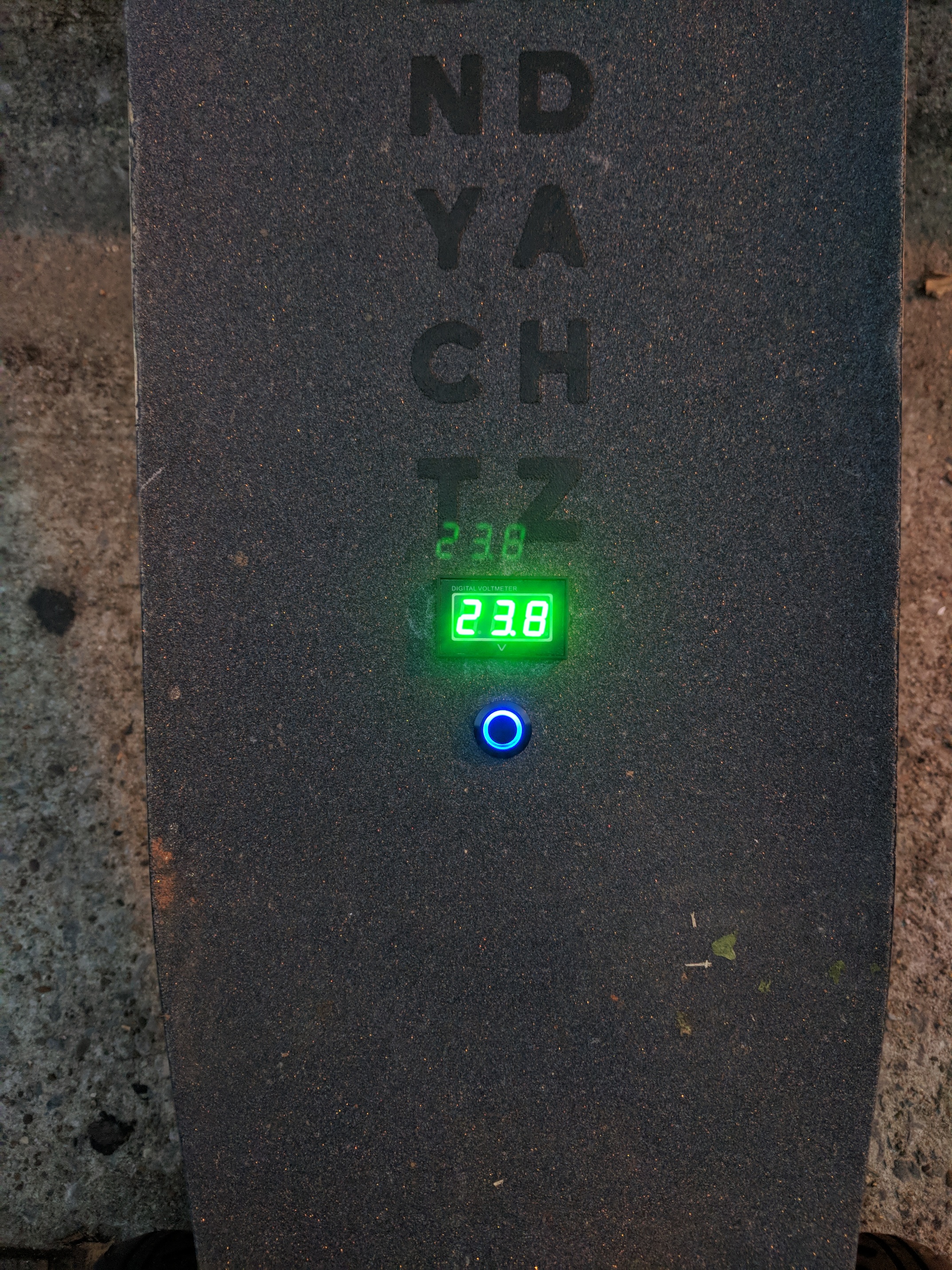
Let me start by saying I’ve disassembled all the major components and can’t figure this out. My voltage meter is going down to 23v when I hit the E-Switch, up to a normal 40v when I turn it on.
I’ve removed the switch and resoldered the leads. I resoldered the led power leads on the switch. Neither made any difference. I’m thinking I may have a BMS issue. Can anyone confirm this for me?
I had a similar problem when the BMS would power on and off which created something similar to PWM and made my voltage roughly double. in my case it was poor connection of the balance leads which caused the bms to turn on and off constantly i guess that it turned on checked if the problem is present then shut down and back to start
I don’t think it’s a balance leads issue, I didn’t pull them and resoldered but I checked the voltage on each block, it was normal. Thanks for the info though.
I’m guessing it’s a BMS issue, but maybe the switch circuit. I’m gonna replace the switch tomorrow to rule that out.
I did not know that. I’ve never heard if a BMS E-Switch failing, I would have assumed it would be as common as anti-spark switch failures.
If it’s not the switch itself and the BMS still.operates correctly I’ll prolly put an anti-spark loop key in and call it a day. I mostly use discharge only these days so is loop keys a lot anyways.
See the reason a bms eswitch likely doesn’t fail as it has all these voltages and gates in series with one another. So it can take the lowvoltage of a 1cell or a group of 2 or 3 cells at a time and increase the voltage across the gate… Trying to step down high voltage to control a gate is hard…but when you have 12 cells and 12 different voltages to work with…
Where a typical antispark has 1…
Likely one of the fets in the BMS is failed open… likely the one connected to your 6th cell based on the voltage your seeing…
I believe most BMS’ have a bunch of high voltage mosfets in parallel, directly placed to limit the LOAD (12s). Why do you think each series has its own mosfet? EDIT: I understood what you meant now.
@mmaner if you want to get serious with the tests you could desolder the on-off button. Then you could observe the behaviour keeping 2 switch wires shorted, and then insulating each of them.
If in both cases the lcd doesnt turn off, the bms cannot be used for discharging anymore.
@Deckoz do you say that bmss take the low voltage of a couple series because you have seen this in an existing design?
I am curious because cheap chinese mosfets draw quite some power for operating and having 10 of them being powered just from 1 series all the time could cause some balancing issues.
Also to the possible problem list there would be that if the balancing cable that powers the fets came off, the bms would loose power. So all of safety function would depend upon that particular cable.
I didn’t read through everything here so forgive me if this has all ready been said.
I have a few different BMS’s with an eSwitch and the voltage in the off position is around 24v but it isint try voltage from what I understand. It will power the voltage meter because it dosnt draw very many amps but my VESC is still off. Is that what is happening?