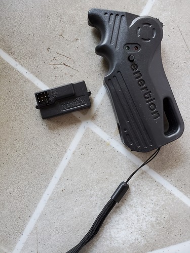
Hi Guys, Uploaded this in the newbie thread but considering the fact that i have all the parts and everything i figured id make a new thread.
Bit of context, about 2-3 years ago I tried to build an electric skateboard, bought all the parts, drew the diagrams, aaaand as you can guess it failed. Pretty badly. If I recall correctly I shorted the BMS (connected the batteries in the wrong order -> saw smoke -> BMS showed no resistance anymore, I think that means its dead right?). Since then the project sorta lost momentum and its been laying in my closet. Not wanting to live with that kind of failure, I recently booted up the project. Unfortunately, it seems like my tech is a bit outdated, and I really dont want to repeat the same mistakes. I’d appreciate help of any kind, ESPECIALLY with the circuit diagrams and compatibility (more on that below).
Here’s what I have:
Batteries: 12s LiPo
VESCs: FocBoxes (if I recall correctly)
RC: enertions remote
Motors:
Drivetrain:
Board + enclosures:
Power switch:
Cursed BMS:
(ignore the duct tape and stuff)
I’ve invested a lot of time and money, and I really want to see the project rolling (no pun intended), but I am woefully inadequate (18 years old, no engineering degree or anything), so if someone with more experience can help me out, that would be wonderful.
If someone can whip up a circuit diagram that includes how everything connects (batteries to controllers to motors, with switches and balance charging capabilities, idk how that looks in the diagram) I’d be SUPER grateful (the diagrams I made/found sorta killed the project last time).
BTW, the focboxes are connected via canbus: do I just connect the remote receiver to the master? for that I need a male to male servo cable (right?), that connects to what 3 pins on the receiver? all 3 BIND pins, or one of each pin (1 bind, 1 ch1, and 1 ch2)?
Any and all replies welcome
Thank You!
@kavic5150 recommended using a RC style balance charger instead of a BMS, after looking up what that is (checked out the iCharger X12) it seemed ideal, but I don’t know how the boards circuit would look (both logically and physically, in the diagram, and literal connectors to the charger for example). Any input on the matter would be great (ideally the batteries won’t leave the enclosures to charge, back then I bought a charger and connectors that I planed to put in the enclosures, that still possible with this type of battery charger?)


