But if you want a motor…
how about this? 56$ http://www.hobbyking.com/hobbyking/store/__18126__Turnigy_Aerodrive_SK3_5065_236kv_Brushless_Outrunner_Motor.html
the problem is that this motor not send to spain…
finally i buyed this: http://alienpowersystem.com/shop/brushless-motors/alien-5065-fr-sensored-outrunner-brushless-motor-270kv-2000w/
what do you think? i want to use it with: FTV 120A ESC http://www.banggood.com/FVT-CBWI120A-ESC-Brushless-Speed-Controller-For-110-and-18Series-RC-Cars-p-985970.html x2 5200mah battery 11.1 25C (6S i think?) http://mistertao.com/beta/pages/item/520711463085.html i weight 60 kg (133lbs)
1 Like
Sounds good! I would suggest starting your own thread so other people can track the build
1 Like
Update: Board has been running smoothly in the last couple weeks, blew a cell with some problems while charging but the new battery worked just fine. when i went through the charging accident though, I blew my wire adapter that enabled me to charge two batteries at once. I then decided it was time for a total upgrade on my board’s wiring. I cut everything up and managed to solder on some xt60 connected that I picked up at a nearby hobby store.
However the newest problem occurred when I tried to add xt60 connecter to my batteries. The gage of my battery wires is 10, while the xt60 supports nowhere near that, it’s too small. As a result, I am looking for a solution that will allow me to solder xt60 connectors to my 10 gage batteries. Should I solder thinner wires to the existing wire? Should I clip part of the copper and use that as a thinner connection? Any help would be appreciated. Thanks!

You can solder 10 gauge with XT 60. It just sticks out a bit.
1 Like
I went ahead and tried it. Had to cut off a bit of the wire and use minimal solder to tin, but it worked pretty well. Unfortunately I don’t have pictures because it got dark, but it’s running smoothly so far. Thanks!
Another update:
Finished more adapters for the batteries, now the entire system uses xt connectors! (I’m surprised I was able to solder the batteries without them blowing up  ) Anyways, now I have three adapters since my ESC is Xt90:
Xt90 to Xt60 for running one battery
Xt90 to Xt60s in series for two batteries
Xt60 to 2 Xt60s for running batteries in parallel
) Anyways, now I have three adapters since my ESC is Xt90:
Xt90 to Xt60 for running one battery
Xt90 to Xt60s in series for two batteries
Xt60 to 2 Xt60s for running batteries in parallel
Just tested every one of them, they all work flawlessly!


The next upgrade I plan to make is with the controller. The Quanum one that I currently use has been a bit sketchy all along, so I’m going to go with that people seem to think is the most reliable: the Gt2B mod. Hopefully that upgrade will come within the next month or so

2 Likes
Did you end up using 12 AWG or 10 AWG?
I was able to make it work with the 12 AWG, although it took a little while longer
That is a nice decision! Just to inform you: GT2E is the newer version but not many people know it and think GT2B is the standard… GT2B and GT2E are more or less equal. There is also a GT2E Mod
Well, i think BadWolf and Mad munkey only fit gt2B. They are more or less equal, but not totally.
what are the benefits of using a GT2E instead of GT2B?
Do you happen to have a link for the GT2E mod? If so, I would happily take a look
Looks cool… Is there anyone who made a video or maybe a topic showing how? You say the electronics are smaller, I’m not sure how it would go if I just tried to figure it all out from scratch
Just use the tutorial for the GT2B mod and apply it to the GT2E. There wont be much of a difference.
@mccloed @psychotiller could you pls explain why you need to cut the red balance wire on the negative side? ill be running the same set up but is going to be an 12s (4 3s) connecting 2 3s for a 6s on onw side and the same on the other so, this is what i designed so i can charge it from outside the enclosure and this is the firs time i read about the leads, good thing i read it before puting everything together
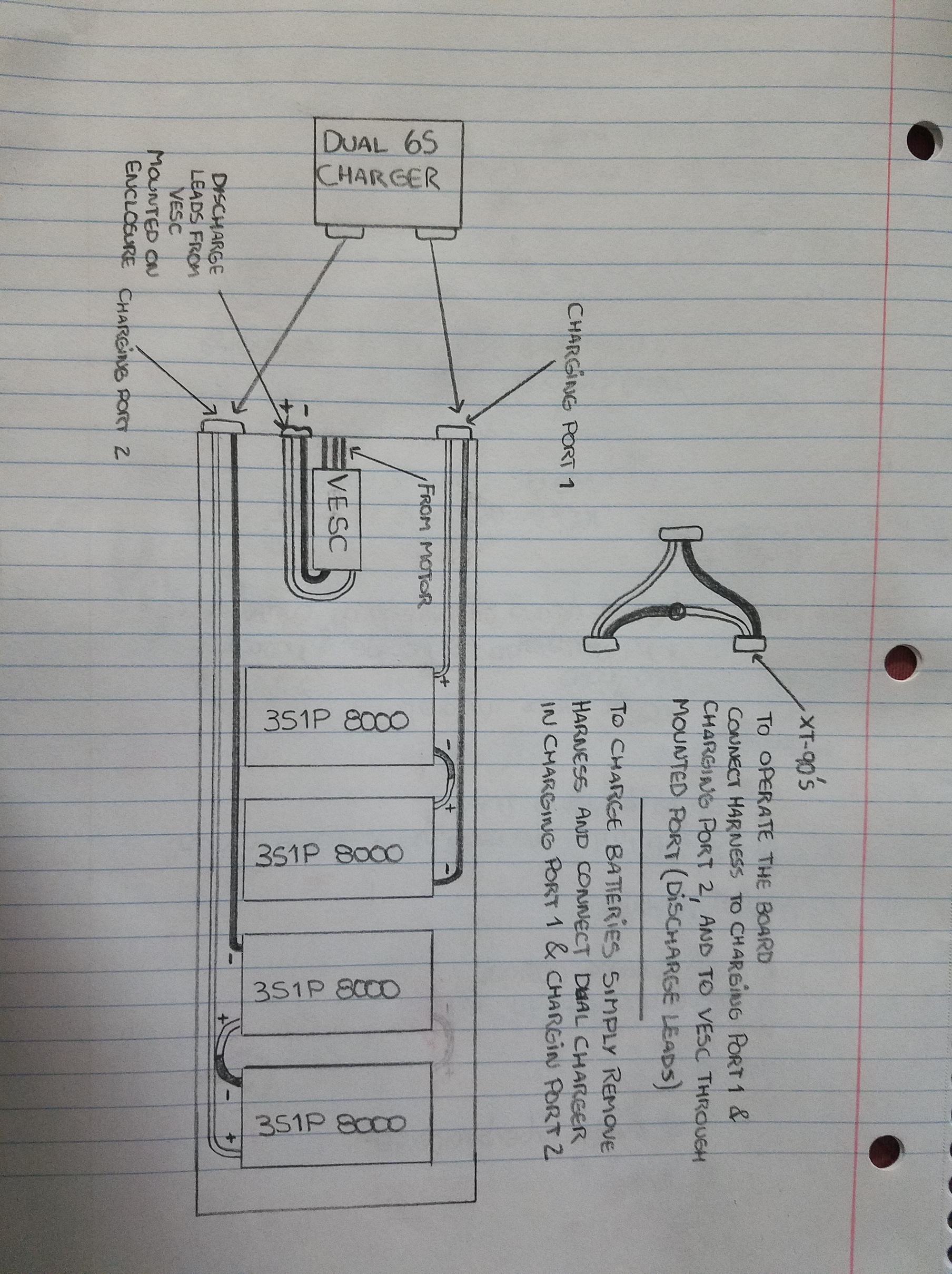
also if anyone can tell me where is the right place for an anti spark xt-90s, in the picture it shows the the discharge leads have a mounted connection on the enclosure to goes to the vesc but i forgot about the on/switch from DIY (in the website it says that this switch has an anti spark built in) does this mean i dont really need a Xt90s at all>?. so basically that port is going to be connected to this switch and then inside the enclosure the switch to the vesc @torqueboards maybe you can help me with this one?